Disassembly report: Eurocom 24W DC power adapter
Yunxing Time:2023-08-03 10:15:39
The charging head network has obtained a 12V adapter from Eurocom, which uses a replaceable pin design to meet the shipping needs of different countries. The adapter supports 100-240V input and 12V2A output, which should be used for mobile hard disks or monitoring devices according to the output power. Here is the dismantling of this adapter to see the internal workmanship and materials.
Before the charging head network also disassembled the Eurocom 65W USB-C power adapter, Eurocom 100W dual USB-C gallium nitride charger, Eurocom 65W USB-C power adapter and other products, welcome to check.
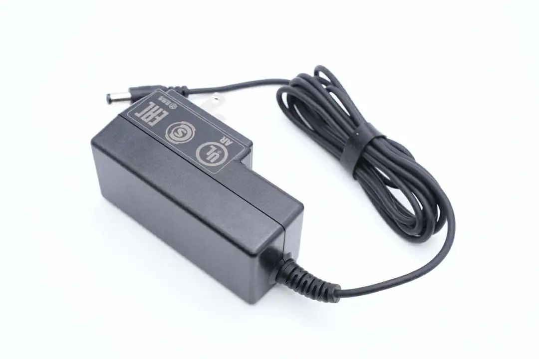
Exterior of the Continental 12V adapter
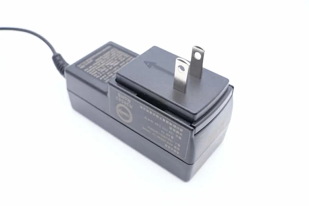
The adapter is a 7-figure design, the pin part is slightly convex, the body shell is frosted and anti-fingerprint, and the corners are rounded.
The adapter body is relatively long, and the vertical plug design is made, which will not occupy the row plug when used, which is praised.
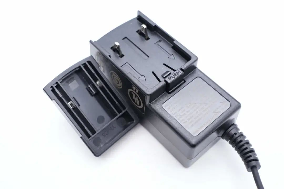
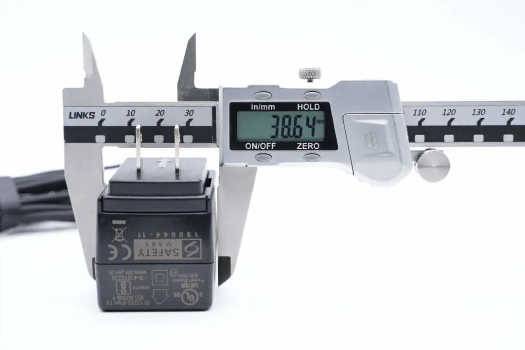
The adapter is equipped with fixed gauge pins that are raised but removable.
There is a "PUSH" message on the shell, the pin can be removed by pressing, and the buckle is fixed.
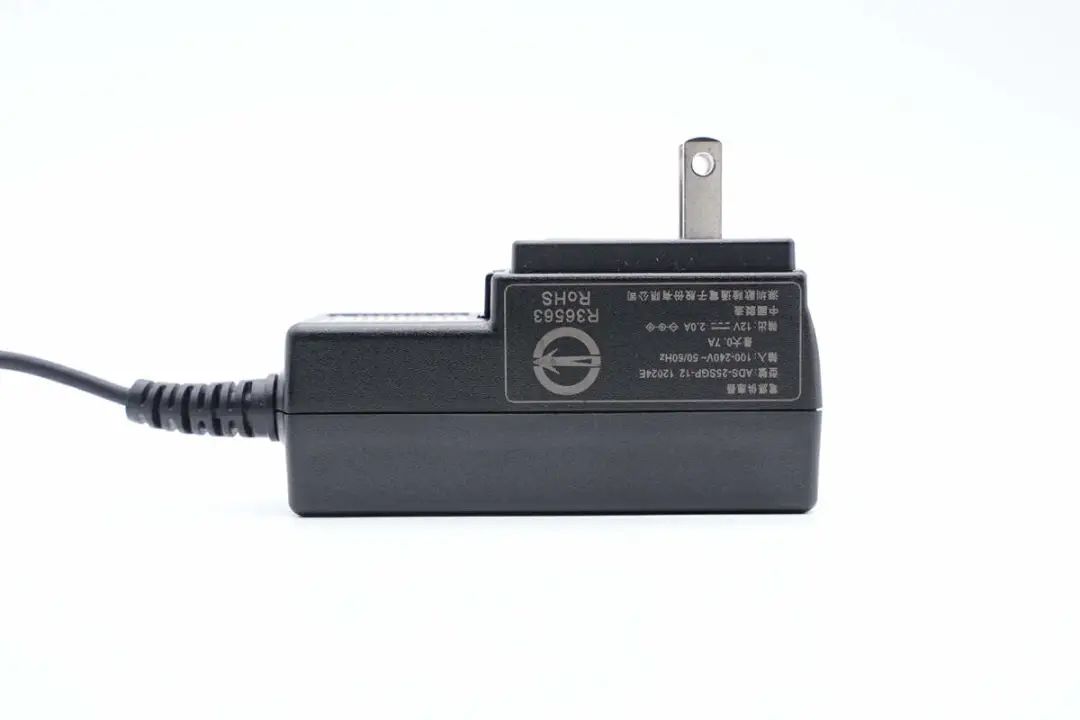
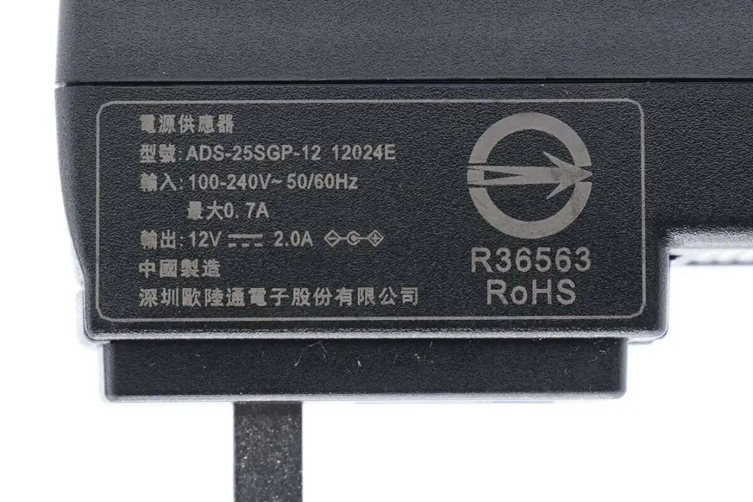
Adapter parameters are printed on the side of the body.
Adapter model ADS-25SGP-12 12024E supports 100-240V to 50/60Hz 0.7A MAX input and 12V2A output.
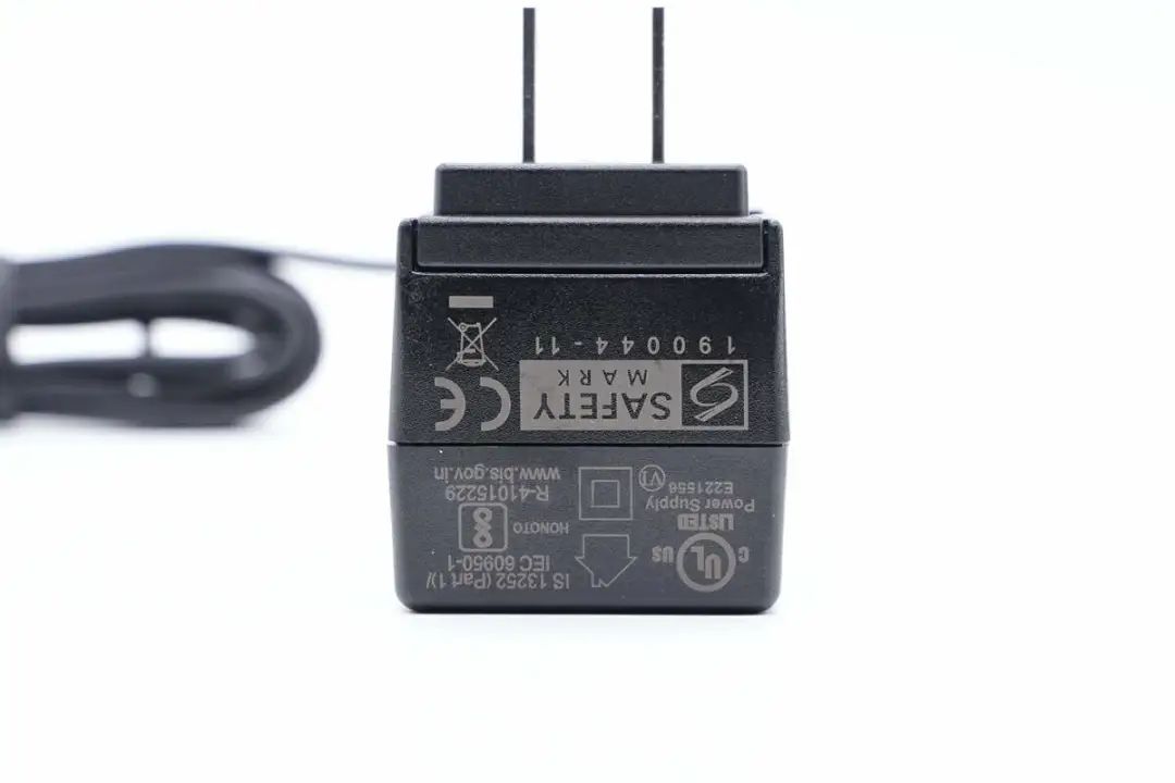
The end is printed with CE and UL certification marks.
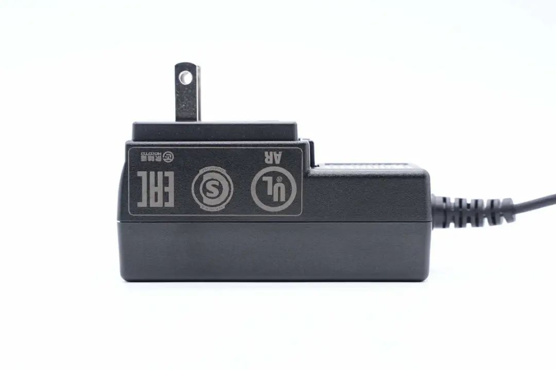
The other side is printed with UL and EAC certification marks.
The thinner part of the shell is printed with the product specification in English.
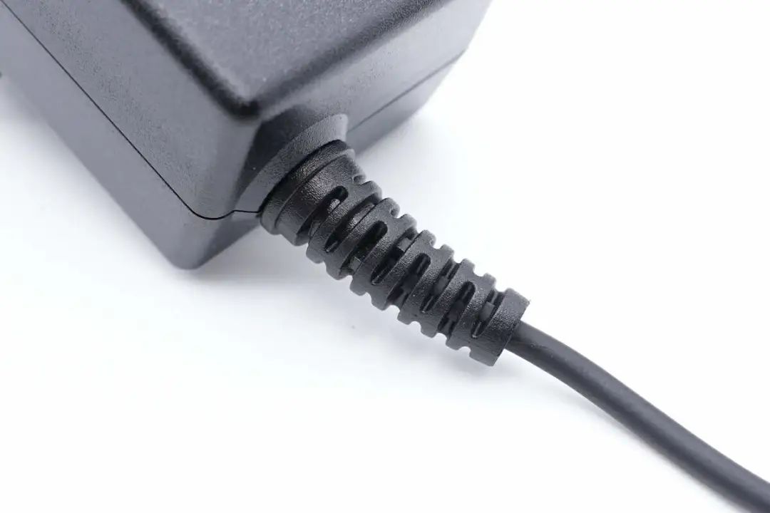
The output cable is designed for bending protection.
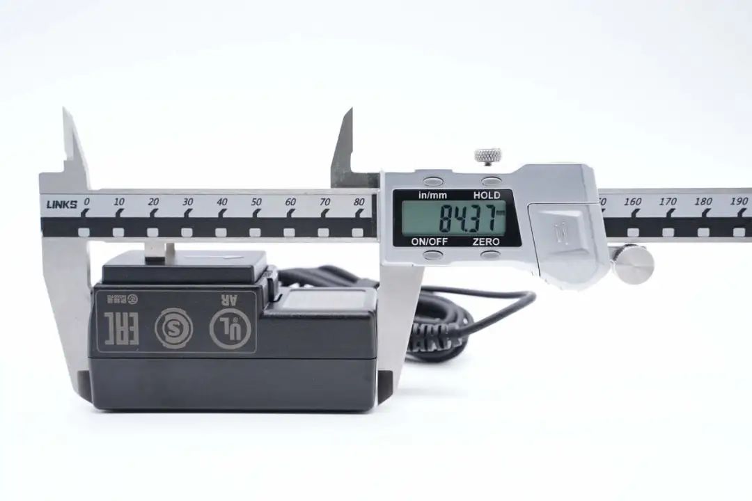
The measured length of the adapter body is 84.37mm.
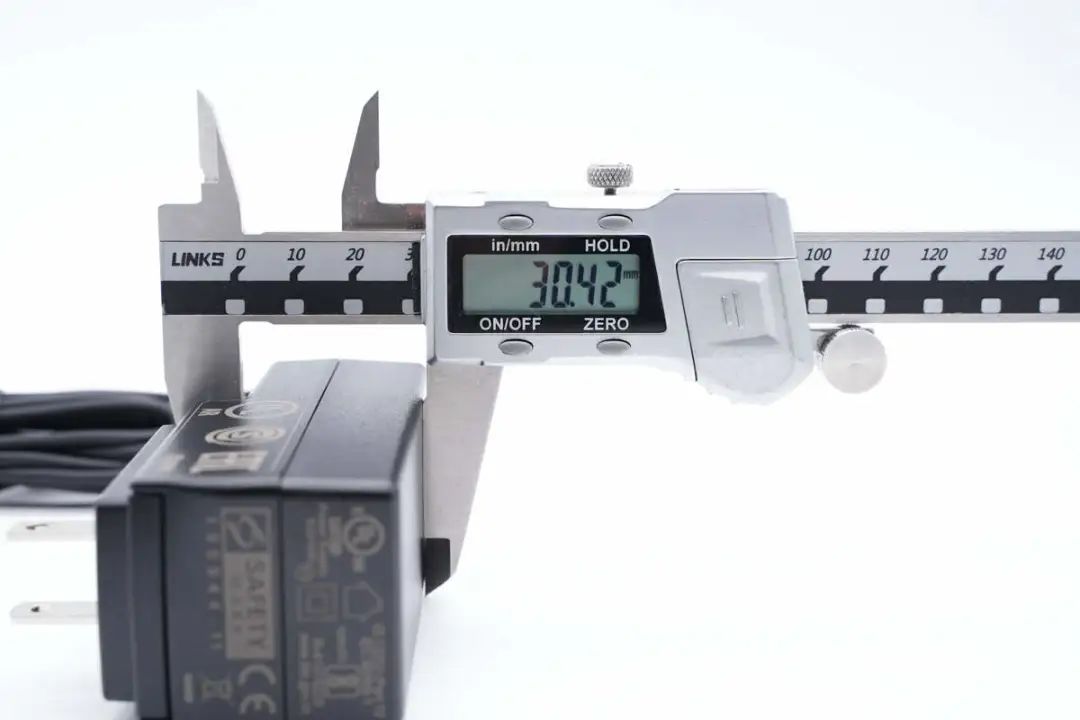
The non-pin part is 30.42mm thick.
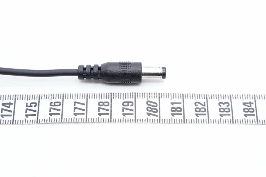
The length of the DC output line is about 1.8 meters.
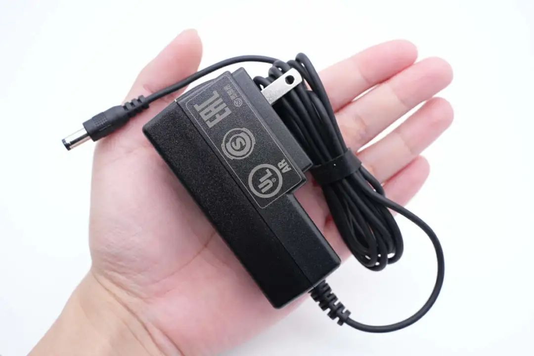
The size of the adapter in your hand is intuitive.
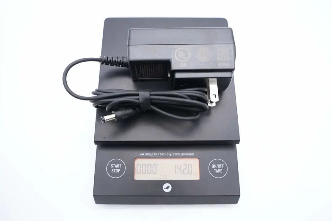
In addition, the weight of the adapter was measured to be about 142g.
Eurocom 12V adapter disassembled
After having a basic understanding of this adapter, the following charging head network will disassemble it in detail, and see how the material work of the product is.
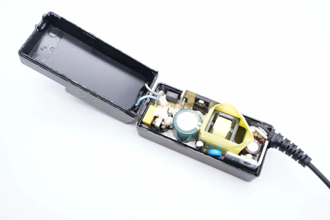
Disassemble the power supply along the upper and lower cover joints, glue the input and output lines, and fix the PCB inside the shell.
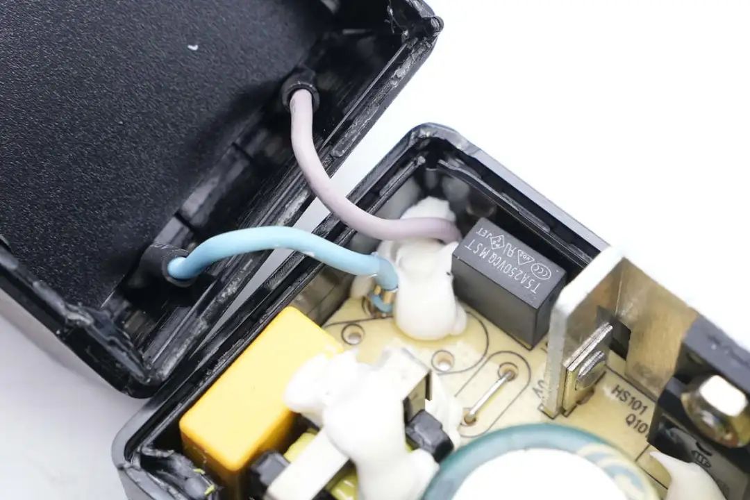
The cord end terminal of the AC input conductor is welded, and the solder joint is reinforced with adhesive.
Take out the PCBA module from the shell, the heat sink of the PCBA module is fixed in the primary and secondary, and the PCB is fixed with the shell.
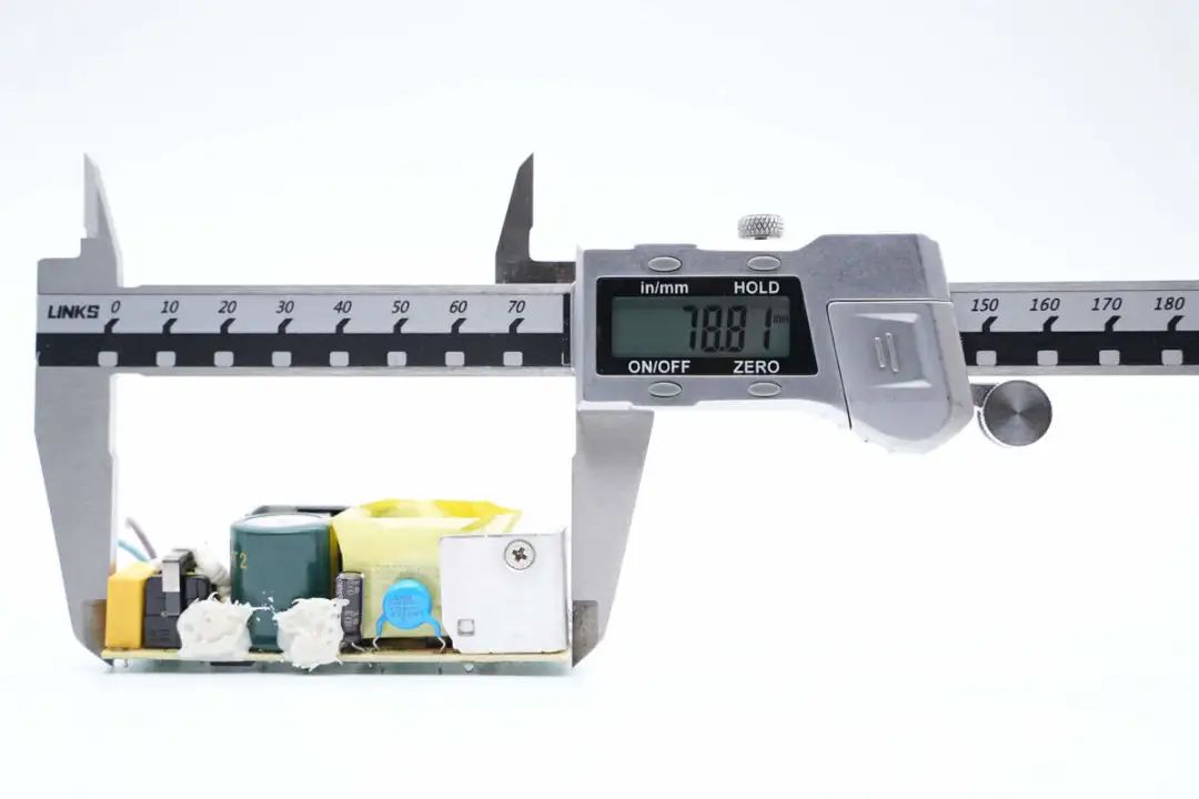
使用游标卡尺测得PCBA模块长度约为78.81mm。
The PCBA module width is approximately 32.23mm.
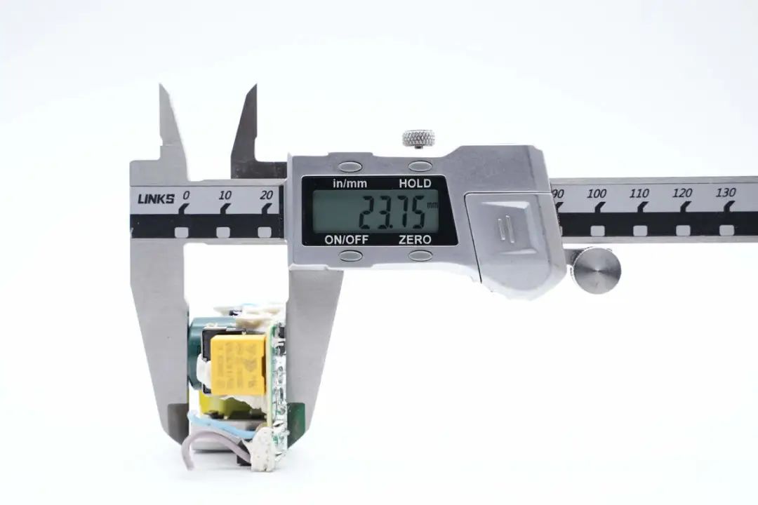
The thickness of the PCBA module is approximately 23.75mm.
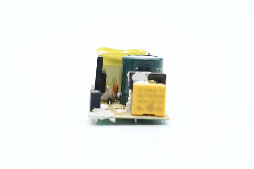
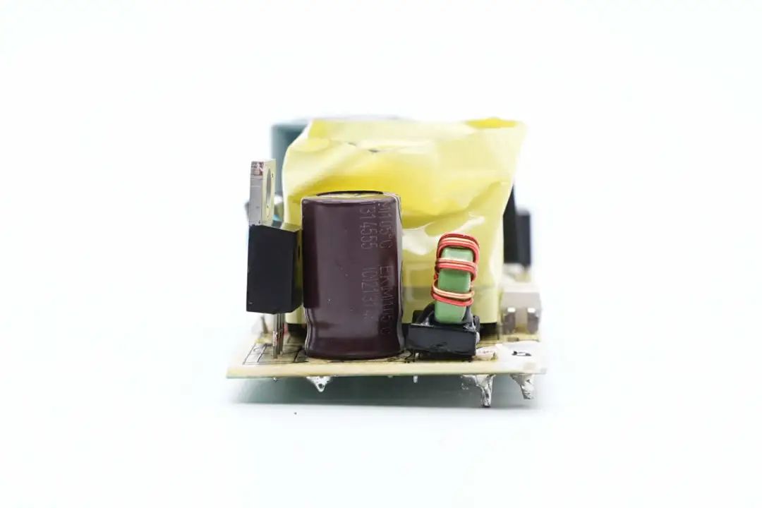
PCBA module front view, the left side is the input, welded fuse, common mode inductor and safety X2 capacitor, the right side is welded high voltage filter capacitor and primary switch tube. The magnetic core of the transformer on the right side is wrapped with tape insulation, the optocoupler is welded above the transformer, and the Schottky rectifier tube on the right side is the output filter capacitor and filter inductor.
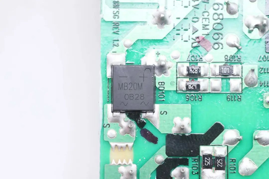
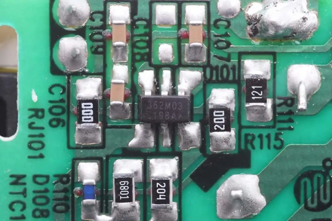
Back welded rectifier bridge, primary power chip, black line to distinguish primary and secondary areas. The adapter is a flyback topology, fixed voltage output, below we start from the input side to understand the information of each device in the adapter.
Input welded fuse, safety gauge X2 capacitor, common mode inductor, primary switching tube and high voltage filter capacitor.
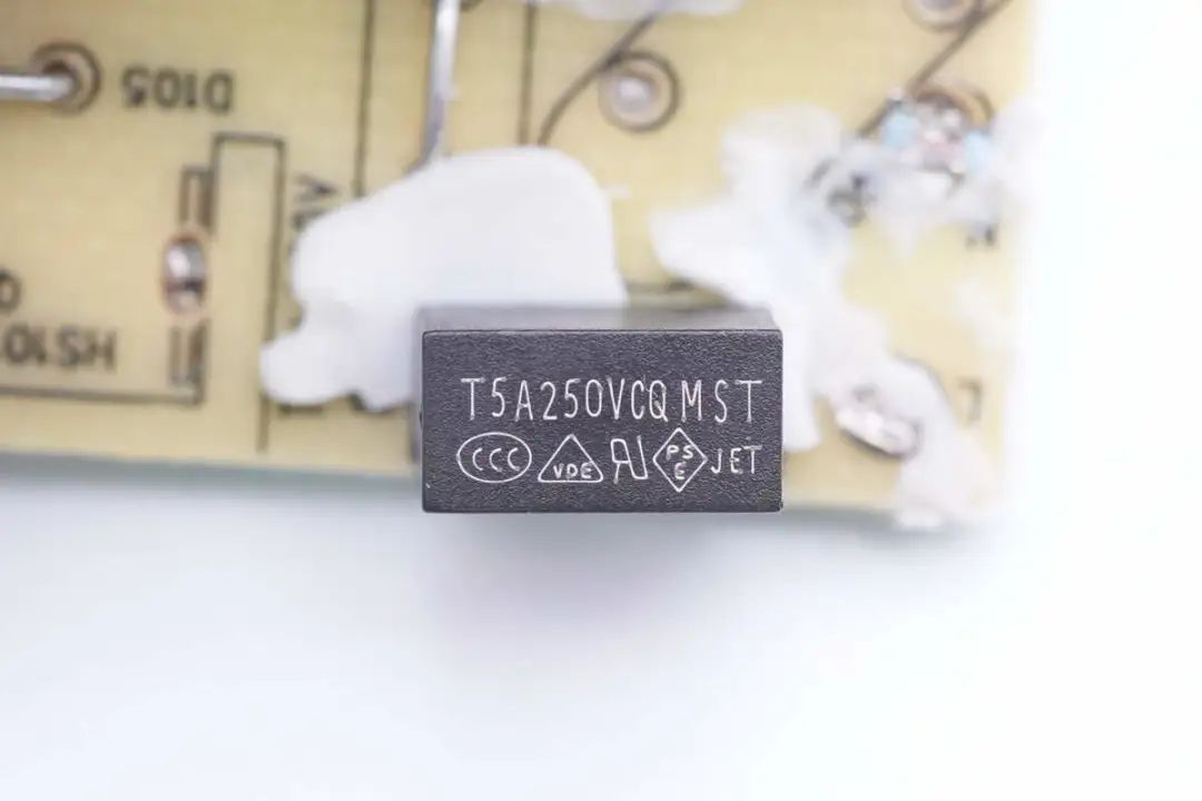
The input fuse comes from CONQUER Merit, MST series subminiature delay fuse, specification is 5A 250V.
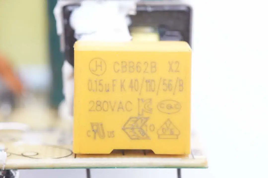
The safety gauge X2 capacitance is 0.15μF.
The common mode inductors are wound with an insulating skeleton.
Input rectifier bridge screen printing MB20M, the specification is 2A 1000V.
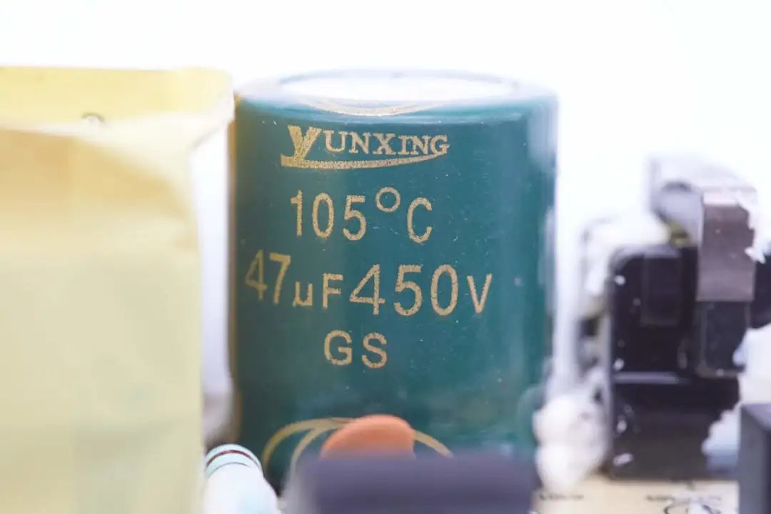
The high voltage filter capacitor comes from Cloud Star, the specification is 47μF450V, and the heat resistance is 105℃.
The primary master chip, model OB2362, is an adaptive high performance flyback controller that supports CCM and QR operating modes and is optimized for high energy efficiency and low standby power consumption.
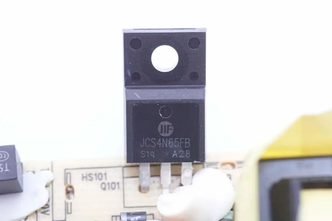
The primary switch tube is from Jilin Huawei, model JCS4N65FB, voltage 650V, resistance 2.4Ω, TO220F package.
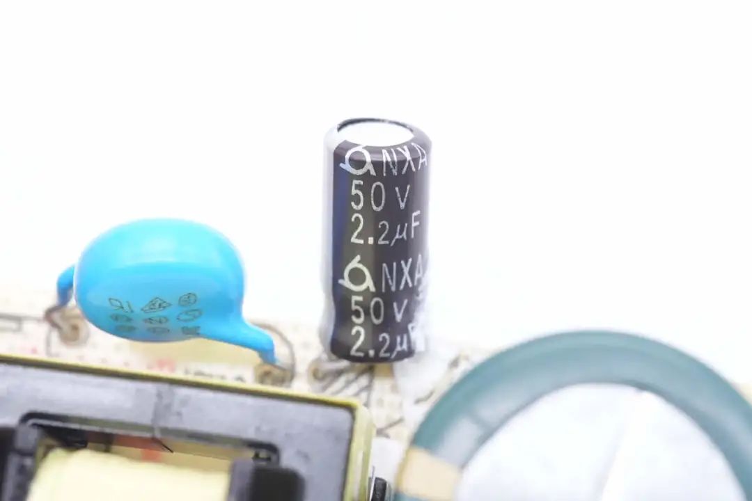
The filter capacitor for the main control chip is 50V 2.2μF.
Transformer close-up, magnetic core wrapped tape insulation.
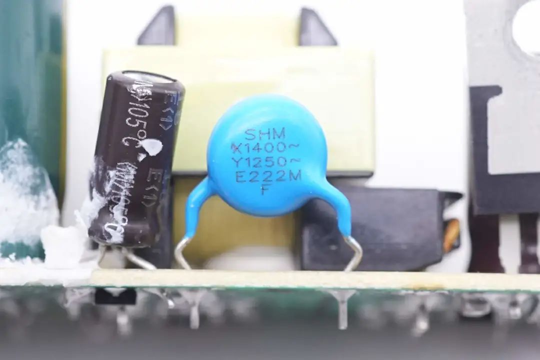
The blue Y capacitor comes from the Honming electron.
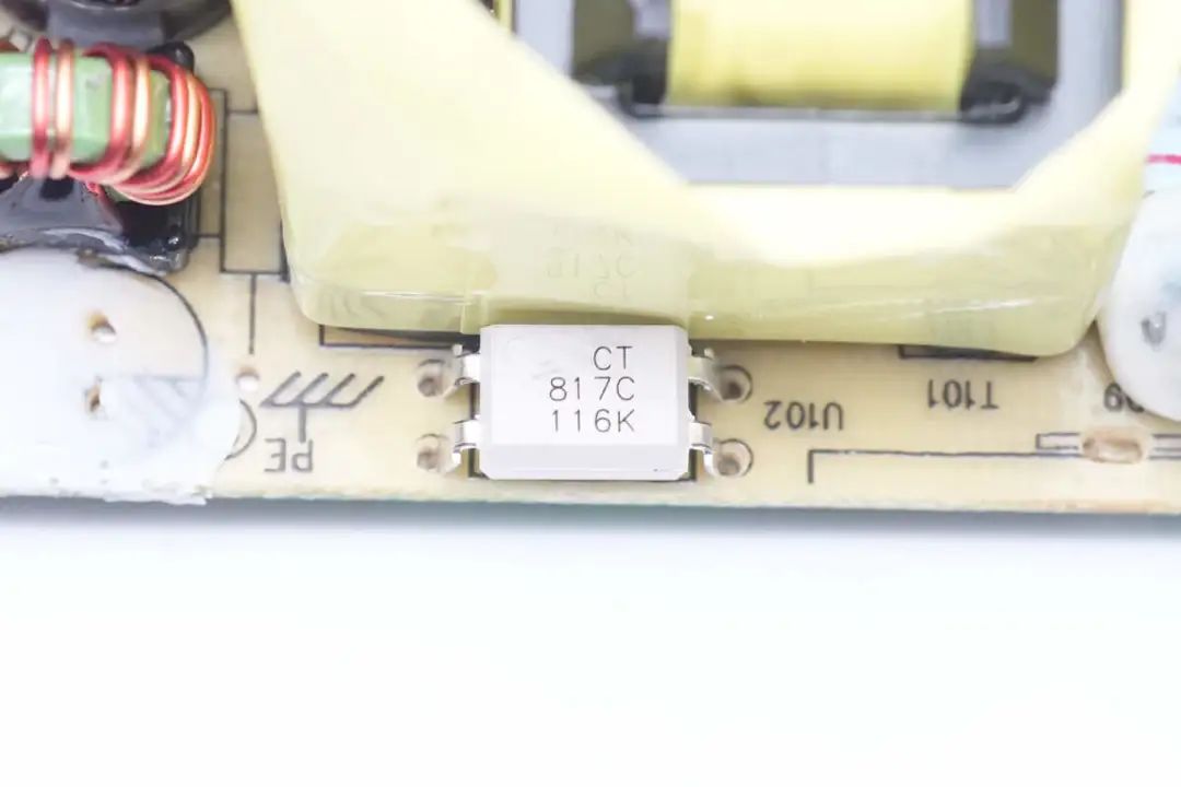
The CT817C optocoupler is used for output voltage feedback.
The output end is welded with rectifier tube, filter capacitor and filter inductor.
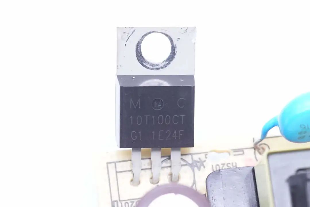
Due to the low efficiency requirements, Schottky diode rectifier is used, silk screen 10T100CT, 100V 10A, and TO220 package is used.
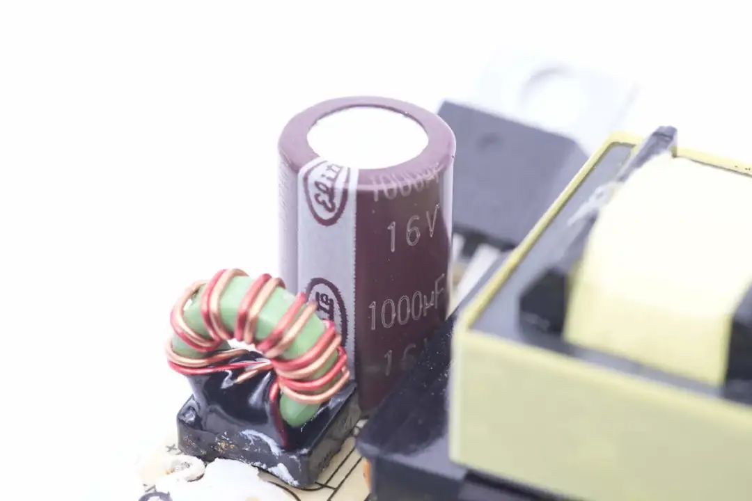
The output filter capacitance is 1000μF 16V.
Filter inductor bottom welded insulation bracket.
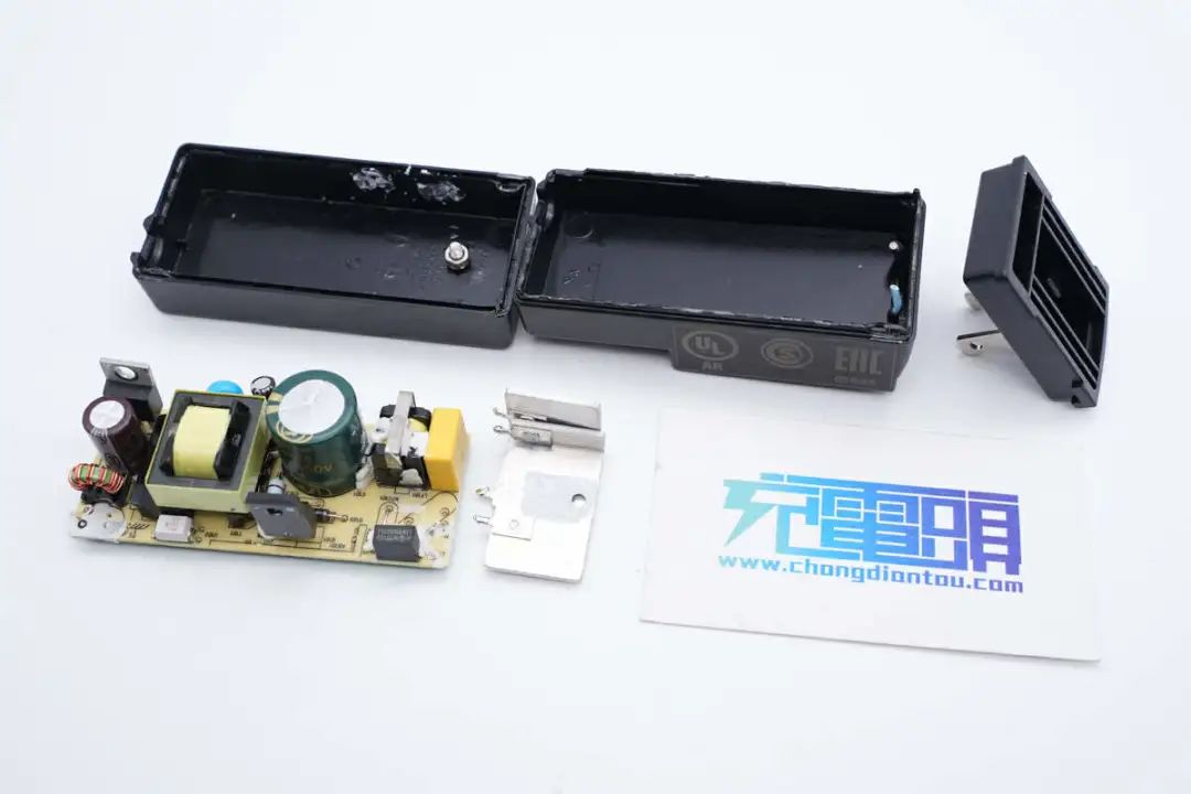
Take it all apart. Get a family photo.

